This is the third and final article in a small series aimed at understanding the basics of firmware programming by taking apart the “hello-world” in embedded systems: turning on an LED.
In the first article of this series, we tried using AI to generate us a minimal LED-blinker. We learnt how GPIO pins work and that we have to enable one of many peripheral clocks to turn them on. Without examining the linking and compilation process, the code looked fine. Yet it still didn’t work.
In the last article, we took a (de)tour of the layout of the STM32H5, particularly the parts involved in the boot process and controlling the hardware, including how the BOOT0 signal is used to set the boot location and that we need to make sure our vector table is front and center when the CPU starts reading from that boot location.
With all of the knowledge we’ve gained so far, it seems like we should be just a few lines of code away from the most minimal software necessary to get that damned LED blinking!
However, on a chip like the STM32H5, there are thousands of things that might be misconfigured. How would we find out which of those myriad complex electrical components have the wrong value at reset time? What if the board itself is broken, or we’ve just totally misunderstood some key concept? How would we know?
To find out what those last few lines could be, we’re going to now change our strategy and do what we wanted to avoid in the first place: building the app the “official” way. We’ll use the example code from STMicroelectronics and whittle it down until we have what we need, replacing any C code with assembly, and manually linking the assembled code to make sure we have a full understanding of where each byte lives on the device.
As bloated as the example software will prove to be, this is a fantastic opportunity to also learn about the ST ecosystem, and how we’d probably want to structure our code for more complex apps. That being said, we won’t lose focus of our goal here: to have a working example with as few moving parts as possible. So let’s roll up our sleevs and dive in.
Taming the Leviathan
I spent a lot of time (like, 2 hours!) downloading the STM32CubeIDE and STM32CubeMX software, a process that required accepting at least 3 EULAs, 2GB of downloads to get the software, a bunch more in-app updates, getting confused with version numbers, and scattered documentation to say the least.
The CubeIDE is an Eclipse-based IDE that just hasn’t aged too well. Personally, as someone who’s on the journey of making Neovim my home, I was delighted to discover that we don’t need the CubeIDE. Although the tutorial material I could find didn’t make the distinction between the two very clear.
CubeMX is also java-based, complete with entirely custom file-pickers that make it feel out of place on your OS and also don’t have the full functionality you might be used to… I also encountered this strange quirk where the screen-resolution setting was set so low that I almost couldn’t navigate the app after first installing it… It is, however, what will ultimately generate the example code for us. From the ST website:
STM32CubeMX is a graphical tool that allows a very easy configuration of STM32 microcontrollers and microprocessors, as well as the generation of the corresponding initialization C code for the Arm® Cortex®‑M core or a partial Linux® Device Tree for the Arm® Cortex®‑A core, through a step-by-step process.
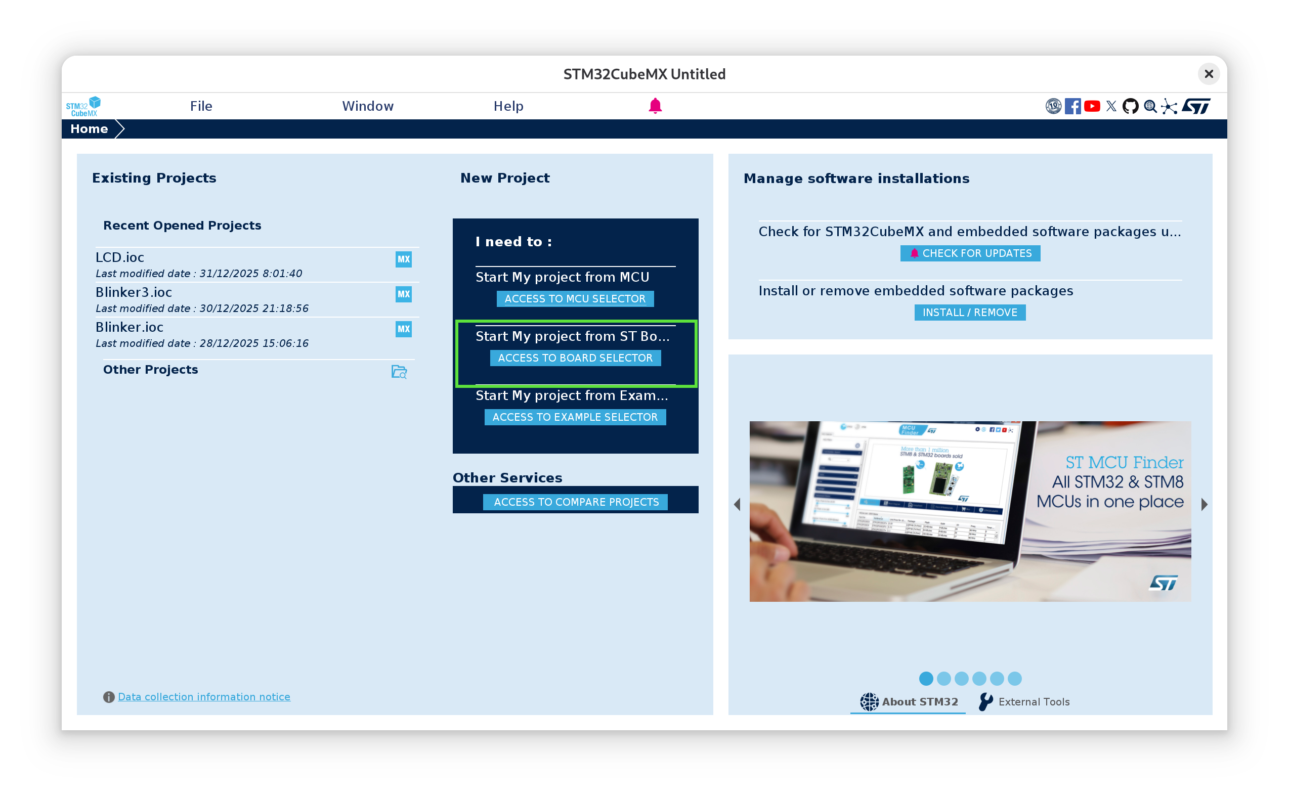
So let’s go ahead and download that. Once installed, generating our LED app is relatively straight forward. We’ll open the app and select “Start My project from ST Board Selector”
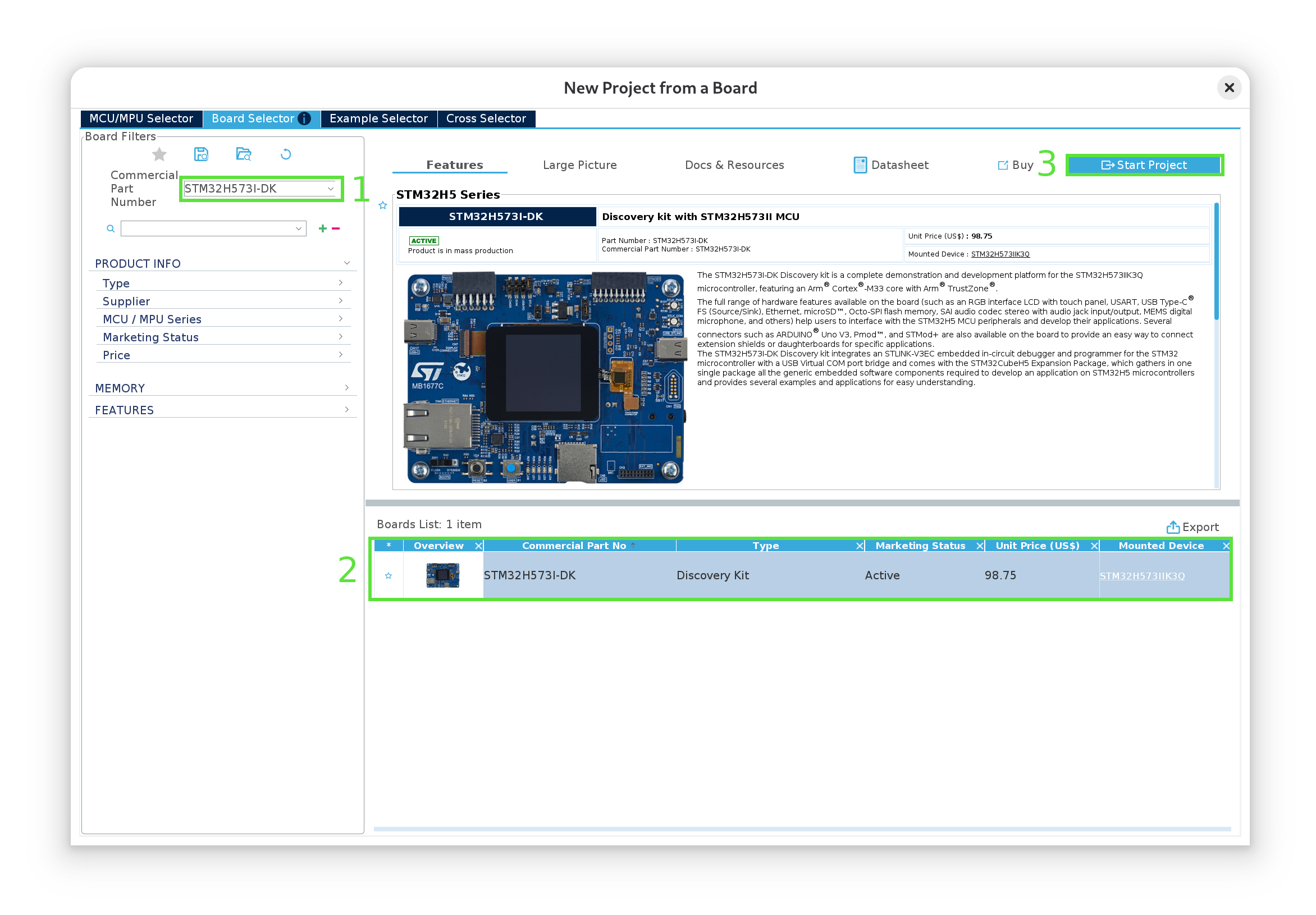
Then we’ll type in the name of our board (1), select it (2) and click “Start Project” (3):
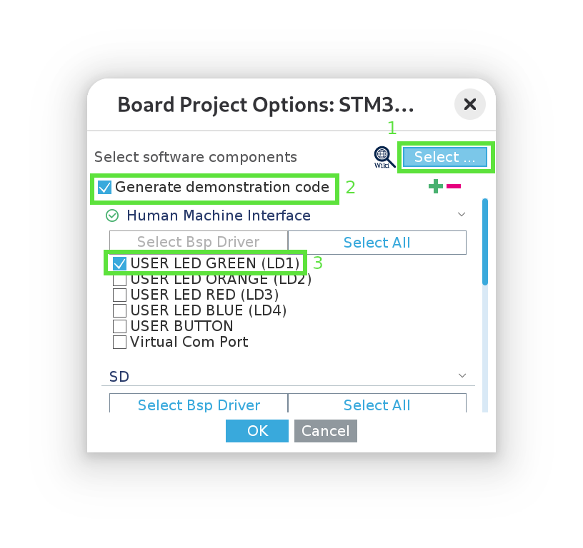
Select “without trustzone activated” when prompted. Then, in the next popup window, unselect all examples (1), select “generate demonstration code” (2) and select “USER LED GREEN (LD1)” (3):
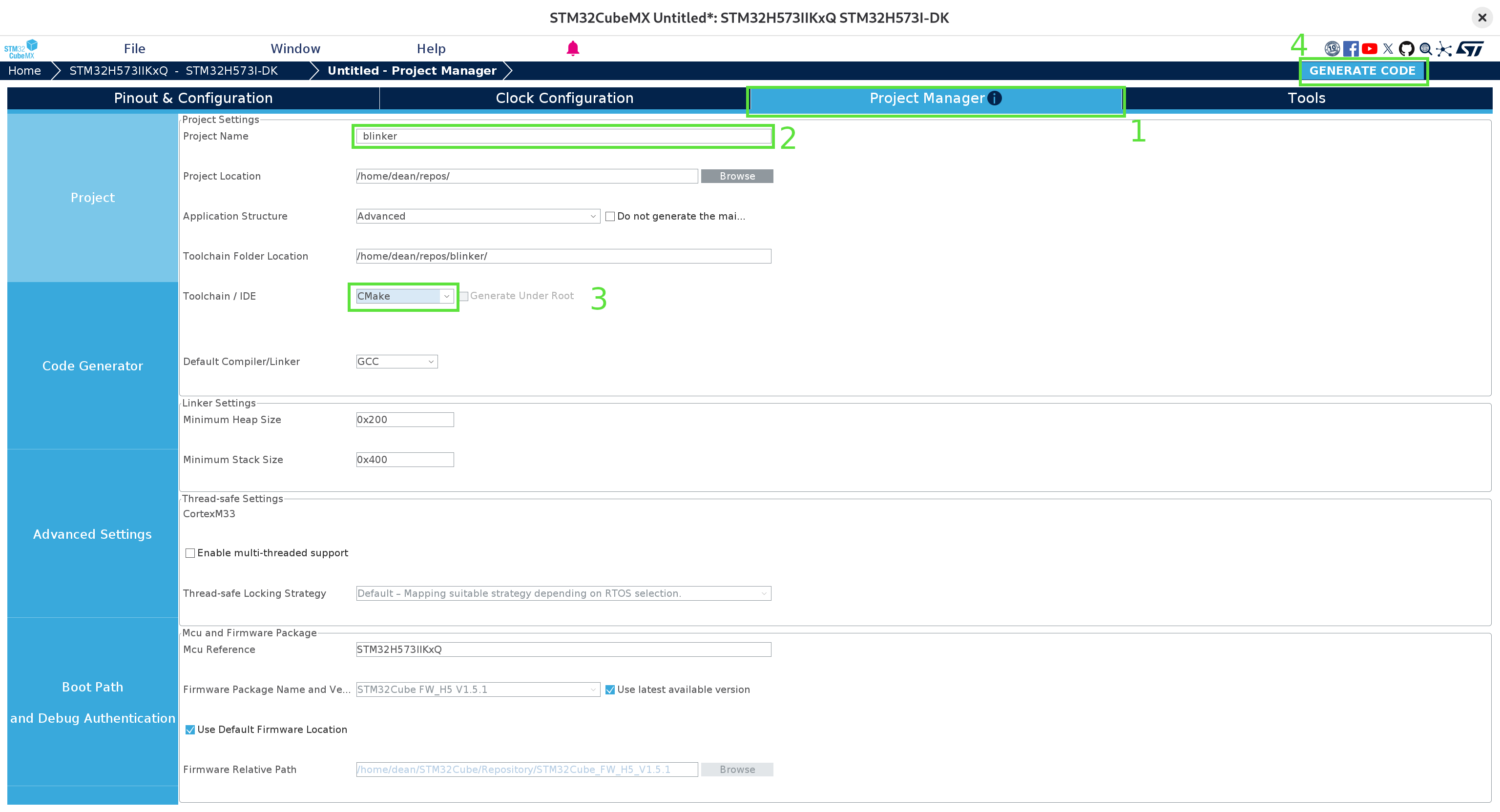
Wait for the UI to render, then: go over to the “Project Manager” tab (1), fill in the project name (2) (and project location, if necessary), ensure CMake is the selected toolchain (3), and then generate the code! (4):
Dismiss the warning about the ICACHE (we don’t really need to optimize anything here) and wait for the code to be generated. At this point, we can close CubeMX and navigate to the location we provided. The project should look something like this:
.
├── blinker.ioc
├── cmake
├── CMakeLists.txt
├── CMakePresets.json
├── Core
├── Drivers
├── startup_stm32h573xx.s
├── STM32H573xx_FLASH.ld
└── STM32H573xx_RAM.ld
Now we have a simple CMake project we can compile! We’ll first generate the build system from CMake using the provided Debug preset in CMakePresets.json:
cmake --preset Debug
In order to get code completion and full clangd support, we now just need to add a link from the root of the repository:
ln -s build/Debug/compile_commands.json compile_commands.json
And finally, so that we only have to run a single command to compile and flash the code, we’ll create a build.sh file that contains all of the steps to run on each build:
# build.sh
set -euox pipefail
cmake --build --preset Debug
arm-none-eabi-objcopy -O binary build/Debug/blinker.elf blinker.bin
STM32_Programmer_CLI -c port=SWD --erase all
STM32_Programmer_CLI -c port=SWD -w blinker.bin 0x08000000 -v -rst
There’s a little bit going on here which I neglected to mention in part 1. The main thing to keep in mind is that the first line compiles and links the code, and the final line flashes the binary to memory location 0x0800000 (the beginning of the FLASH region on the STM32H5). We’ll dive deeper into these steps later on.
Flash devices have a limited number of write cycles before they begin to lose the capacity to reliably store data. Usually, this is measured in the 100s of kCycles, so it’s unlikely we’ll get close to this limit when flashing the device by hand. Just don’t go running this script in a busy loop!
Running this now, we get one compilation error:
Core/Src/main.c:46:1: error: unknown type name 'TS_State_t'
   46 | TS_State_t TS_State;
      | ^~~~~~~~~~
It turns out the fix for this is just to remove the offending line. Running our script again, we finally see what we’ve been waiting for now all this time:
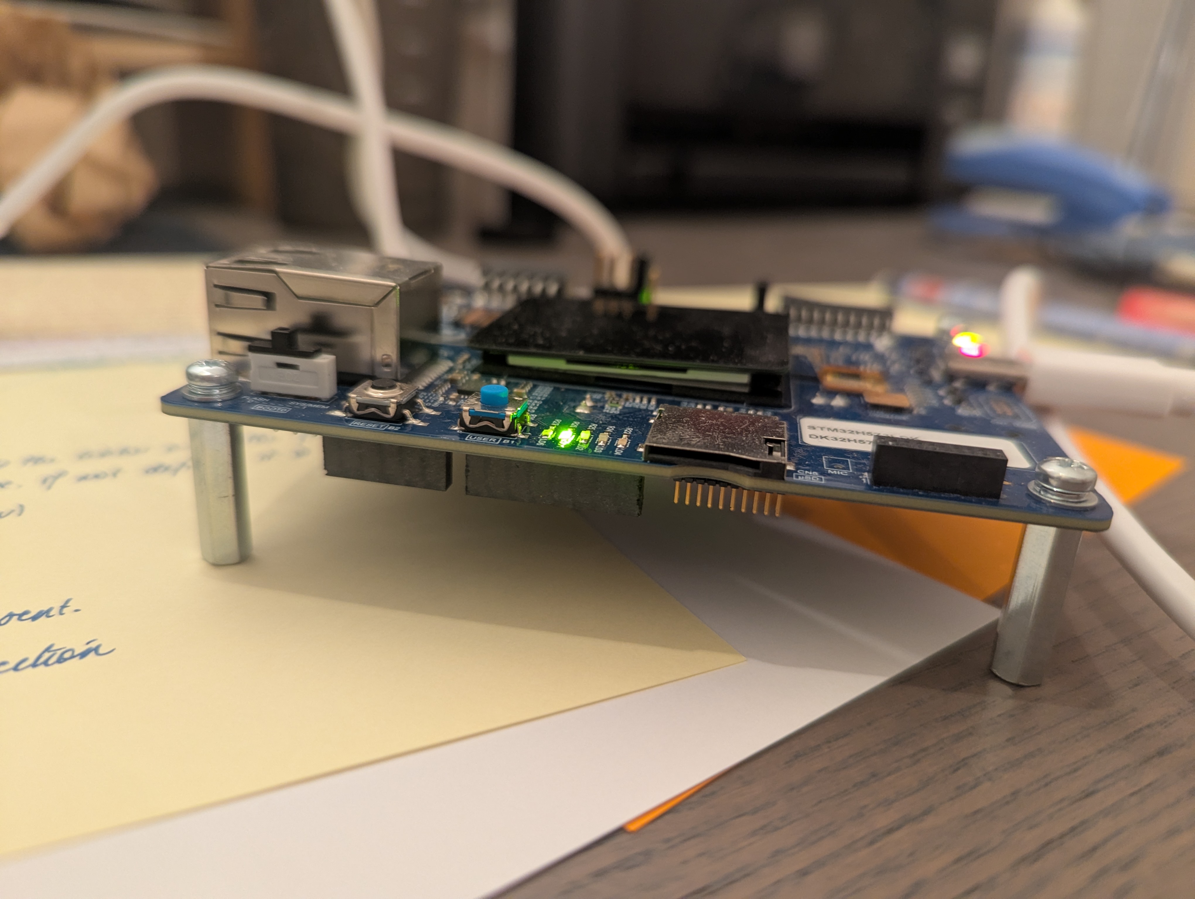
Stripping away the cruft
Okay, so we’ve proven to ourselves that the device works and it is in fact possible to turn on the LED.
Astute followers along might have noticed that roughly 9.21KB of binary machine code are flashed onto the device. Our original, minimal sample from part 1 contained only 56B. Looking at the output of cloc from the root of our directory:
-------------------------------------------------------------------------------
Language                     files          blank        comment           code
-------------------------------------------------------------------------------
C/C++ Header                    80          19087          43907          75018
C                               35           8621          21334          31356
Assembly                         1            161             67            485
Linker Script                    2             68             96            308
Markdown                         3             42              0            213
Text                             3             32              0            181
CMake                            4             58             50            173
JSON                             1              0              0             38
Bourne Shell                     1              0              0              4
-------------------------------------------------------------------------------
SUM:                           130          28069          65454         107776
-------------------------------------------------------------------------------
We see over 100kLoC just to get an LED running! Of course, most of this is here so that people can get started building applications much more complex than just turning on an LED, including HALs (hardware abstraction layers) and BSPs (board support packages), that standardize a lot of the interaction with the hardware to allow for portability. But all of this completely obfuscates how the device works under the hood, so let’s step through the code, starting from the generated main.c file and try to get a grip of what all this code is doing!
Stripping away all of the comments, our main function boils down to this:
/* Core/Src/main.c */
#include "main.h"

__IO uint32_t BspButtonState = BUTTON_RELEASED;
__IO uint32_t TouchPressed = 0;

void SystemClock_Config(void);
static void MX_GPIO_Init(void);

int main(void)
{
  HAL_Init(); // Reset of all peripherals, Initializes the Flash interface and the Systick.
  SystemClock_Config(); // Configure the system clock
  MX_GPIO_Init(); // Initialize all configured peripherals
  BSP_LED_Init(LED_GREEN);
  BSP_LED_On(LED_GREEN);
  while (1);
}
A lot of the comments in the generated source code are littered with USER CODE BEGIN|END. This is to ensure that the code generation from CubeMX can be run again without overwriting anything we’ve added to the project.
In a future article, it would be great to dive into how to read the clock-tree diagram, how to select and initialize clock sources, and perhaps even how to read the clock signals using an oscilloscope or frequency detector just to get a feel for how the clocks work. However, for the sake of our sanity, we’re going to shortcut a lot of that for now and just ask ourselves a few simple questions based off of the comments next to the first 2 lines in our main function.
We know that based on our understanding of how the vector table is set in part 2, that the Cortex-M33 starts in privileged thread mode and reads from the vector table location, pointed to by the VTOR signal. It then reads the location of the ResetHandler and begins executing the code pointed to by that entry of the vector table. So if that’s the case, then: how can the CPU execute any code on reset if the clocks haven’t been initialized?
Similarly, if flash memory is one of the valid boot locations we can set with the BOOT0 pin, then: how could anything be booted from flash if it were waiting to be initialized on reset?
The answer is simple, however the comments in the code might not lead one straight to it: there are defaults configured into the chip that it uses on reset! For the STM32H5, it uses the HSI internal clock source, configured to run at 32MHz (see RM0481, section 11.4). (the prescalers before the HCLK and PCLKs are also configured to scale the clock by a factor of 1, so, although our AHB clock needs to be enabled, when it is, it should also be set to 32Mhz).
Similarly, the flash memory is already configured in such a way that it can be used without any extra configuration.
We can easily confirm both of these things by doing something a little wild: deleting first two lines, recompiling and reflashing our code!
/* Core/Src/main.c */
#include "main.h"

static void MX_GPIO_Init(void);

int main(void)
{
  MX_GPIO_Init(); // Initialize all configured peripherals
  BSP_LED_Init(LED_GREEN);
  BSP_LED_On(LED_GREEN);
  while (1);
}
And the LED still turns on! (as a little sanity check, change LED_GREEN to LED_RED just to make sure you see a difference).
At this point, it doesn’t cost much to see which lines are at all necessary to get our LED switched on. Commenting out each one and reflashing, we see that we get down to just the following code:
/* Core/Src/main.c */
#include "main.h"

int main(void)
{
  BSP_LED_Init(LED_GREEN);
  BSP_LED_On(LED_GREEN);
  while (1);
}
And we’re down to 2.35 KB!
Which tells us that the default clock configuration is in fact perfectly fine for controlling the LEDs. As we expected in part 1, all we have to do is initialize the LEDs and turn them on.
This confirms our intuition that the problem then must lie in compilation or linking! Let’s, however, continue to strip out parts we don’t need to get back to the minimal code we started with in part 1.
Hammering in how MMI/O works
I’ve talked about it a lot in the previous articles, but it still feels important enough to mention it again from as many angles as possible: memory mapped I/O works by simply setting memory values!
To see this in the generated code, let’s dive into the BSP_LED_Init() function. Here, I’ll only show the parts actually relevant to our GPIO pin PI9 (LED1), removing any control structures that check the LED id:
/* Drivers/BSP/STM32H573I-DK/stm32h573i_discovery.c */
int32_t BSP_LED_Init(Led_TypeDef Led)
{
	GPIO_InitTypeDef  gpio_init_structure;

	LED1_GPIO_CLK_ENABLE();
	/* Configure the GPIO_LED pin */
	gpio_init_structure.Mode = GPIO_MODE_OUTPUT_PP;
	gpio_init_structure.Pull = GPIO_NOPULL;
	gpio_init_structure.Speed = GPIO_SPEED_FREQ_HIGH;
	gpio_init_structure.Pin = LED_PIN [Led];
	HAL_GPIO_Init(LED_PORT[Led], &gpio_init_structure);
	HAL_GPIO_WritePin(LED_PORT [Led], (uint16_t)LED_PIN[Led], GPIO_PIN_SET);

	return BSP_ERROR_NONE;
}
And let’s here double click on the LED1_GPIO_CLK_ENABLE() macro, an alias for __HAL_RCC_GPIOI_CLK_ENABLE(), which is defined as:
do { \
	__IO uint32_t tmpreg; \
	SET_BIT(RCC->AHB2ENR, RCC_AHB2ENR_GPIOIEN); \
	/* Delay after an RCC peripheral clock enabling */ \
	tmpreg = READ_BIT(RCC->AHB2ENR, RCC_AHB2ENR_GPIOIEN); \
	UNUSED(tmpreg); \
} while(0)
And SET_BIT is defined as:
#define SET_BIT(REG, BIT) ((REG) |= (BIT))
which is doing nothing other than modifying the value at memory location REG. That’s all MMIO is! Nothing to be sent off anywhere from the programmer’s perspective, the single, machine-code write instruction (which we’ll see later) is what triggers the peripheral’s controller hardware!
For more complex applications, be aware that after enabling a peripheral clock, at least 2 cycles of that clock (it may be configured to run at a different speed to the CPU) have to pass before the peripheral’s registers can be accessed (see RM0481, section 11.4.16). Supposedly trying to read from the clock register also forces this synchronisation, which is what the macro above is doing.
The peripheral in question is the RCC (reset and clock control) module that we explored in part 1, the RCC_AHB2ENR. Notice in the __HAL_RCC_GPIOI_CLK_ENABLE macro, that the STM32 HAL organises the registers for each peripheral into structs, such as the RCC_Typedef struct, where each field is carefully typed to be the width of each register on the peripheral. The RCC instance of this struct is simply a C-pointer cast that starts at a particular address offset. This means that field access of this struct instance gives us the memory location of that register in that peripheral! Pretty smart.
I think we’ve belaboured long enough the point that a lot of this code is unnecessary and the issue lies elsewhere. So take my word for it when we can unpack all the macro definitions and strip away all unnecessary configuration functionality to arive at the the exact same functionality Claude gave us in part 1:
/* Core/Src/main.c */
#define RCC_BASE      0x44020C00UL
#define GPIOI_BASE    0x42022000UL

#define RCC_AHB2ENR   (*(volatile unsigned int *)(RCC_BASE + 0x8CU))
#define GPIOI_MODER   (*(volatile unsigned int *)(GPIOI_BASE + 0x00U))

int main(void)
{
	RCC_AHB2ENR |= (1 << 8);  // Enable GPIOI clock (port index 8)
	GPIOI_MODER &= ~(3 << 18); // Clear the mode (change to 16 to try the red LED)
	GPIOI_MODER |= (1 << 18); // Set to general-purpose output (change to 16 to try the red LED)
}
And now we’re down to 1.25 KB with the LED still on! Note that we don’t even have to actually set the output value of the pin, simply enabling it is enough. Presumably the default value is high in output mode.
(it also looks like we don’t have to worry too much about synchronisation with the peripheral’s clock for our simple use case).
Minimal vector table
So that was a very roundabout way of confirming that the issue in our original code was not with the code itself, but with how it was getting to the device. We know from part 2 that somewhere, somehow, the address of the “reset handler” is taken out of the vector table by the CPU on reset, and the CPU then gets to work on it as the entry point to the entire system. So where is the vector table being filled out?
Let’s look again at our project layout. If you’re with me this far, so far we’ve only modified Core/Src/main.c. The messy guts of the CMake structure are out of scope here, but the other file worth looking at is startup_stm32h573xx.s. And well, would you look at that, it’s in assembly!
Now, there’s a lot going on here, including preparing memory regions and creating all the possible interrupt handlers that hook into some empty C functions in the generated code. But for our purposes, we’re interested in a tiny subset of all of this. Following the same approach of delete and reflash to see that the LED still works, and jiggering things around a bit, we can get the file down to this:
.syntax unified
	.cpu cortex-m33
	.thumb

.section	.isr_vector,"a",%progbits
	.word	0x0
	.word	Reset_Handler

.section	.text.Reset_Handler
	.type	Reset_Handler, %function

Reset_Handler:
	bl main
Notice how the Reset_Handler calls out to our main function, which is being spliced in here somehow. We can take it a step further though. Our main function only updates two registers, so by just taking a quick look at how ARM thumb2 assembly works, we can put the main function right into our Reset_Handler ourselves!
...
Reset_Handler:
	/* Enable GPIOI clock in RCC_AHB2ENR (bit 8) */
	ldr r0, =0x44020C8C      /* RCC_AHB2ENR address */
	ldr r1, [r0]
	orr r1, r1, #(1 << 8)    /* Set bit 8 for GPIOI */
	str r1, [r0]

	/* Configure PI9 as output in GPIOI_MODER (bits 18-19 = 01) */
	ldr r0, =0x42022000      /* GPIOI_MODER address */
	ldr r1, [r0]
	bic r1, r1, #(3 << 18)    /* Clear bits 18-19 (change to 16 to try red LED) */
	orr r1, r1, #(1 << 18)    /* Set bit 18 (1 = output) (change to 16 to try red LED) */
	str r1, [r0]
With those last changes, we’re now down to 160B!
One of the biggest space savers here is that we removed a call to the SystemInit function from the Reset_Handler, a function which is located in Core/Src/system_st32h5xx.c and has some useful documentation around the clock config. Interestingly, we’ve now seen 3 such functions to initialize the clocks before our user code is called!
Notice that our assembly file now also contains 2 lines which define what’s inside the vector table. This is the minimum required for the CPU to find code that it can run (and in fact, we don’t even need the stack pointer here, we only need to leave space for where we would define one).
Linking
Now we’re down to the final mile. How do we go from assembly to machine code that’s flashed to location 0x08000000 on our device?
First off, we’re going to do some housekeeping and remove all code we’re not referencing, which is most of it. I’ll also pull out the exact assembler and linker commands from the build system generated by CMake, and just put these directly in our build.sh file:
set -euox pipefail
arm-none-eabi-gcc -mcpu=cortex-m33 -T "STM32H573xx_FLASH.ld" --specs=nano.specs -Wl,--gc-sections startup_stm32h573xx.s
arm-none-eabi-objcopy -O binary a.out blinker.bin
STM32_Programmer_CLI -c port=SWD --erase all
STM32_Programmer_CLI -c port=SWD -w blinker.bin 0x08000000 -v -rst
Notice how we’re now calling the arm-gcc compiler directly on our startup_stm32h573xx.s file (here gcc is “driving” the assembler and linker) and there is just one other file dependency we can’t get rid of yet. Removing everything else, we’re left with:
.
├── build.sh
├── startup_stm32h573xx.s
└── STM32H573xx_FLASH.ld
Just 3 files! We know all about the first two, but this last dependency we haven’t looked at yet, the linker script STM32H573xx_FLASH.ld.
Linking is an entire universe unto itself, and so for our sanity, and to keep this article from getting even longer than it already is, I’m going to link to a few great references for learning more about it:
- The driving compilers series by Fabien Sanglard, particularly the chapters on compilers and linking,
- A Whirlwind Tutorial on Creating Really Teensy ELF Executables for Linux, by Brian Raiter
From here on out, I’m going to assume at least a passing understanding in the topics covered there. The GNU manual on using ld might also be very helpful in understanding the linker script format.
First off, we’re going to chip away out our linker script to produce something minimal:
MEMORY
{
  FLASH    (rx)    : ORIGIN = 0x8000000,   LENGTH = 2048K
}

SECTIONS
{
  .isr_vector :
  {
    . = ALIGN(4);
    KEEP(*(.isr_vector))
    . = ALIGN(4);
  } >FLASH

  .text :
  {
    . = ALIGN(4);
    *(.text)
    . = ALIGN(4);
  } >FLASH
}
So that now all that’s happening is that the linker is defining the FLASH memory region at location 0x08000000 (we don’t need RAM for our app, so I removed that region from the original script) and then moving the .isr_vector and .text sections to that region, ensuring the starting boundaries for each of these sections are alligned to 4-bytes.
Building our app now, we’re down to just 48B flashed to the device! That’s pretty neat, but there’s still a bit of magic going on. Let’s take a look at the arguments we’re passing to the linker in our build.sh script (pay attention to the -Wl flag)
# build.sh
...
arm-none-eabi-gcc -mcpu=cortex-m33 -T "STM32H573xx_FLASH.ld" --specs=nano.specs -Wl,--gc-sections startup_stm32h573xx.s
...
If we remove -Wl,--gc-sections and rerun, we suddenly get a bunch of errors:
arm-none-eabi/bin/ld: warning: a.out has a LOAD segment with RWX permissions
arm-none-eabi/bin/ld: arm-none-eabi/lib/thumb/v8-m.main/nofp/crt0.o: in function `_mainCRTStartup':
(.text+0x52): undefined reference to `main'
arm-none-eabi/bin/ld: (.text+0x6c): undefined reference to `__bss_start__'
arm-none-eabi/bin/ld: (.text+0x70): undefined reference to `__bss_end__'
arm-none-eabi/bin/ld: arm-none-eabi/lib/thumb/v8-m.main/nofp/libc_nano.a(libc_a-exit.o): in function `exit':
(.text.exit+0x18): undefined reference to `_exit'
arm-none-eabi/bin/ld: arm-none-eabi/lib/thumb/v8-m.main/nofp/libc_nano.a(libc_a-closer.o): in function `_close_r':
(.text._close_r+0xc): undefined reference to `_close'
arm-none-eabi/bin/ld: arm-none-eabi/lib/thumb/v8-m.main/nofp/libc_nano.a(libc_a-lseekr.o): in function `_lseek_r':
(.text._lseek_r+0x10): undefined reference to `_lseek'
arm-none-eabi/bin/ld: arm-none-eabi/lib/thumb/v8-m.main/nofp/libc_nano.a(libc_a-readr.o): in function `_read_r':
(.text._read_r+0x10): undefined reference to `_read'
arm-none-eabi/bin/ld: arm-none-eabi/lib/thumb/v8-m.main/nofp/libc_nano.a(libc_a-writer.o): in function `_write_r':
(.text._write_r+0x10): undefined reference to `_write'
arm-none-eabi/bin/ld: arm-none-eabi/lib/thumb/v8-m.main/nofp/libc_nano.a(libc_a-sbrkr.o): in function `_sbrk_r':
(.text._sbrk_r+0xc): undefined reference to `_sbrk'
So essentially, the section GC is removing code that is referencing things that aren’t there! The clue here is provided by the second reference on linking I provided above. The compiler is actually including a libc implementation (the nano libc, as specified by the --specs=nano.specs flag) which includes a C runtime (the crt0.o object trying to call main). But we removed our main function and just put the logic direclty in our Reset_Handler.
The system calls that our linker fails to find: _read, _write, _close, _exit, etc. were actually provided by the code generated by CubeMX that we deleted a few steps ago. They were to be found in Core/Src/syscalls.c. This just goes to remind us that we have to bring everything we need along with us when doing firmware development!
We can do better than garbage collecting stuff that we don’t need: we can avoid putting it there in the first place by using the -nostdlib gcc flag, so our compiler command becomes:
# build.sh
...
arm-none-eabi-gcc -mcpu=cortex-m33 -T "STM32H573xx_FLASH.ld" --nostdlib  startup_stm32h573xx.s
...
And there we go, no more errors, no garbage collection, and our build is now down to 40B on device! It’s pretty clear now where our 40B are also laid out, starting at address 0x0800000, in two small sections. But do we still need the linker script at all? Can’t we just pack those 40B directly out of the assembler into ready-to-flash binary?
And it turns out, not really… The compiler chain is setup these days so that even the assembler produces input object code that needs to then be run through a linker to produce the output object file that we can then convert into a binary file and flash to the device. The assembly directives themselves aren’t designed to do relocation and if we want to remove the linker script, we have to resort to passing command line options to ensure our two sections are placed at the beginning of the FLASH region. That doesn’t really win us much.
Let’s get a tea
But still, if you’ve made it this far, we’ve seen just how much extra code is included in the official examples from ST, what a bunch of it does, and how we managed to systematically work our way so that in the end we’re only putting exactly the bytes we need onto our device. The final project is 2 source files and a build script. coming in at just 43 LoC!
-------------------------------------------------------------------------------
Language                     files          blank        comment           code
-------------------------------------------------------------------------------
Linker Script                    1              5              0             20
Assembly                         1              5              2             18
Bourne Shell                     1              0              0              5
-------------------------------------------------------------------------------
SUM:                             3             10              2             43
-------------------------------------------------------------------------------
Although we probably wouldn’t want to follow this approach for any application of reasonably complexity, knowing how the device goes from reset to running code through the vector table and Reset_Handler will surely provide invaluable for reasoning about issues in those more ambitious apps.
I didn’t show the original linker code that Claude recommended to us in part 1. Take my word for it, it was pretty close, but it tried putting everything into one text section, didn’t come up with the -nostdlib option, and a few other little quirks that would have been hard to find without us getting all the way here ourselves. Although it got me unstuck in a few places, this project has me feeling a little less worried about AI taking my job anytime soon.
All up, an interesting journey. Thanks for coming along with me!
P.S: we never actually got the LED blinking… but I guess that’ll have to wait for another time 😉