In the bare-bones blinker series, we figured out the minimum necessary code needed to control peripheral devices, going in-depth into how memory-mapped IO works, getting a good sense for how the board and SoC is structured and becoming comfortable with working through the reference manual to find all the information we need.
Turning on an LED, however, requires no debugging. We can see if the app worked by simply observing if the LED turned on. Before we can begin to write any serious applications, we’ll need to expand our debugging toolkit to give us visibility into the inner workings of the processor. We’ll start in this article with printf debugging, and along the way learn a bit more about libc, UART, the USB protocol and the STM32 hardware.
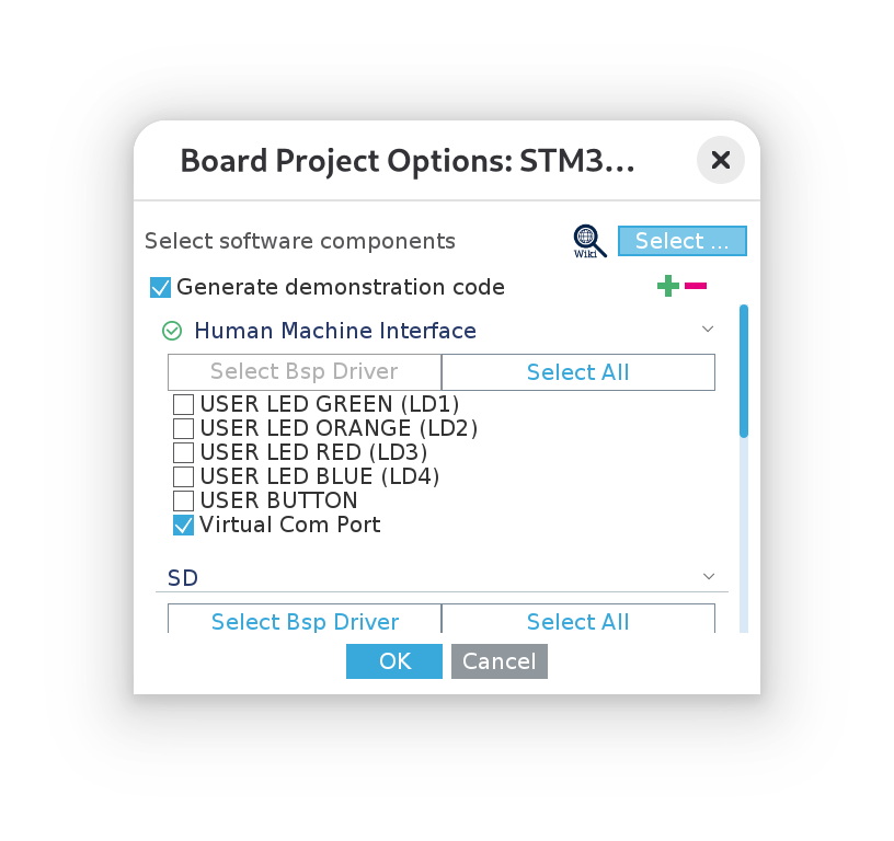
We’ll once again start by using the provided sample code to get a working example and then see if we can cut the code down to really understand what’s going on. We’ll fire up CubeMX and start a new project from the board selector, as we did in the previous article. However, this time, we’re going to start out selecting the “Virtual Com Port” example:
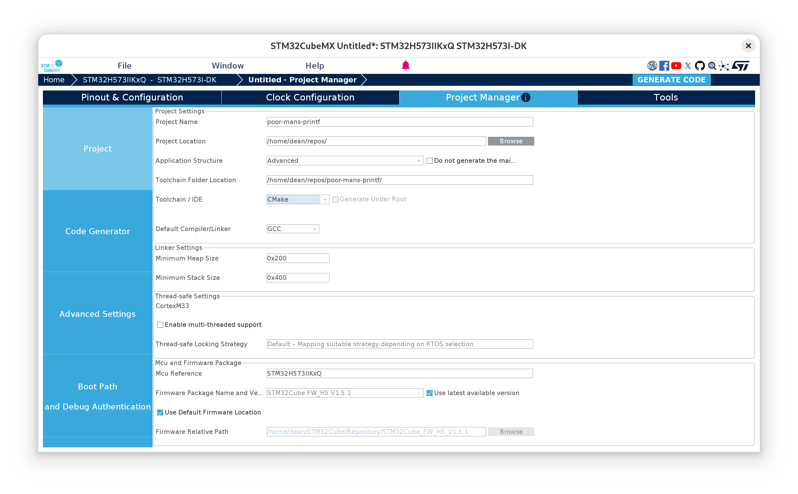
Then we’ll go ahead and give the project a name and once again use the CMake toolchain:
Now we can close CubeMX and set up the LSP for the project by running:
cmake --preset --Debug
ln -s build/Debug/compile_commands.json compile_commands.json
Stripping away all of the comments, this is the main() function the example code has given us:
// Core/Src/main.c
#include "main.h"

COM_InitTypeDef BspCOMInit;
__IO uint32_t BspButtonState = BUTTON_RELEASED;
__IO uint32_t TouchPressed = 0;

void SystemClock_Config(void);
static void MX_GPIO_Init(void);

int main(void)
{
	HAL_Init();
	SystemClock_Config();
	MX_GPIO_Init();
	BspCOMInit.BaudRate   = 115200;
	BspCOMInit.WordLength = COM_WORDLENGTH_8B;
	BspCOMInit.StopBits   = COM_STOPBITS_1;
	BspCOMInit.Parity     = COM_PARITY_NONE;
	BspCOMInit.HwFlowCtl  = COM_HWCONTROL_NONE;
	if (BSP_COM_Init(COM1, &BspCOMInit) != BSP_ERROR_NONE)
	{
		Error_Handler();
	}

	while (1) {
		HAL_Delay(1000);
		printf("Welcome to STM32 world !\n\r");
	}
}
I’ve changed the structure of the main function slightly from the generated example so that we print in the loop with a small delay each time. Otherwise we’d likely miss the first printf and see nothing!
Great, okay, so we’re given a working printf example, ready to go! But… where exactly does it print to? Where do we read the output? Let’s follow the characters to see where they go.
printf and nanolib
printf, as we might already know from regular C-development, is a function defined in the std lib; its interface defined in <stdio.h> (which we find a reference to in our project’s main.h).
As we touched upon briefly in the last article, the Arm GNU toolchain comes with nanolib bundled as the libc implementation. Nanolib is a “configuration variant” of Newlib and depends upon various low-level system calls to be supplied by us. The generated code provides these system calls in Core/Src/syscalls.c.
The actual linking of nanolib into our application after compilation is specified by the rather arcane nano.specs spec file, located under the lib/ directory from the root of the Arm-GNU tools install location. The configuration macros used are defined in include/newlib.h.
I was hoping to be able to trace the call chain from printf through libc to the _write system call that ultimately services it, however, looking at the source code for a while doesn’t exactly offer much clarity due to the heavy use of these configuration macros and indirection. So, rather than waste any more time on this fruitless endeavour, we can convince ourselves that the our _write function is called by simply commenting it out, then compiling the project:
cmake --build --preset Debug

...
arm-none-eabi/lib/thumb/v8-m.main+fp/hard/libg_nano.a(libc_a-writer.o): in function `_write_r':
src/newlib/newlib/libc/reent/writer.c:49:(.text._write_r+0x10): undefined reference to `_write'
The _r suffix of _write_r stands for reentrant. A lot of the Newlib code goes out of its way to be so. However, one criterion of reentrancy is that a reentrant function cannot call a non-reentrant function. This implies our _write() function should be reentrant too!
Anyway, the key take away here is that nanolib depends upon a user-provided set of syscalls, and the one we care about here is _write() in Core/Src/syscalls.c.
Threading the needle
Let’s now step through the different levels of indirection in the generated code. Starting from the _write() procedure:
// Core/Src/syscalls.c
int _write(int file, char *ptr, int len)
{
  (void)file;
  int DataIdx;

  for (DataIdx = 0; DataIdx < len; DataIdx++)
  {
    __io_putchar(*ptr++);
  }
  return len;
}
Then moving to the definition of __io_putchar, my editor takes me to here:
//Drivers/BSP/STM32H573I-DK/stm32h573i_discovery.c

#if defined(__ICCARM__)
/* New definition from EWARM V9, compatible with EWARM8 */
int iar_fputc(int ch);
#define PUTCHAR_PROTOTYPE int iar_fputc(int ch)
#elif defined ( __CC_ARM ) || defined(__ARMCC_VERSION)
/* ARM Compiler 5/6*/
#define PUTCHAR_PROTOTYPE int fputc(int ch, FILE *f)
#elif defined(__GNUC__)
#define PUTCHAR_PROTOTYPE int __io_putchar(int ch)
#endif /* __ICCARM__ */
It’s perhaps not super obvious what’s happening here, but the macro PUTCHAR_PROTOTYPE is used to allow for several different choices of character put function, presumably for different toolchains with different libc implementations and mechanisms for calling out to the syscalls. Since we’re using the GNU toolchain, we’ll trigger the last case in the set of statements. Searching for uses of the macro then gives us the spot we’re looking for:
//Drivers/BSP/STM32H573I-DK/stm32h573i_discovery.c
/**
  * @brief  Retargets the C library printf function to the USART.
  */
PUTCHAR_PROTOTYPE
{
  (void)HAL_UART_Transmit(&hcom_uart [COM_ActiveLogPort], (uint8_t *) &ch, 1, COM_POLL_TIMEOUT);
  return ch;
}
And now we’re starting to get somewhere! printf is relying on UART to transmit characters and, it seems, one particular UART port, the COM port.
To understand which UART this is, let’s take a look at where the hcom_uart struct array is defined.
//Drivers/BSP/STM32H573I-DK/stm32h573i_discovery.c

/**
  * @brief  Configures COM port.
  * @param  COM port to be configured.
  *          This parameter should be COM1
  * @param  COM_Init Pointer to a UART_HandleTypeDef structure that contains the
  *                configuration information for the specified LPUART peripheral.
  * @retval BSP status
  */
int32_t BSP_COM_Init(COM_TypeDef COM, COM_InitTypeDef *COM_Init)
{
...
    /* Set the COM Instance */
    hcom_uart[COM].Instance = COM_UART[COM];
...
}
BSP_COM_Init is called from the main function above, which checks out. (Note the comment regarding that the COM port should always be COM1… more of a constant than a parameter then, if you ask me…)
Now, the COM_UART array is defined further up in the same file:
//Drivers/BSP/STM32H573I-DK/stm32h573i_discovery.c
USART_TypeDef *COM_UART[COM_NBR]   = {COM1_UART};
And COM1_UART is defined in the adjacent header file:
//Drivers/BSP/STM32H573I-DK/stm32h573i_discovery.h
#define COM1_UART                     USART1
There is a subtle shift in terminology here from UART to USART. The S in USART stands for “synchronous”, refering to the fact that USART can operate in so-called synchronous mode. In this mode, a special clock pin is switched on and is used by the “master” node to set the baud rate, so that neither side must agree ahead of time what it should be. But otherwise, their functionality is the same.
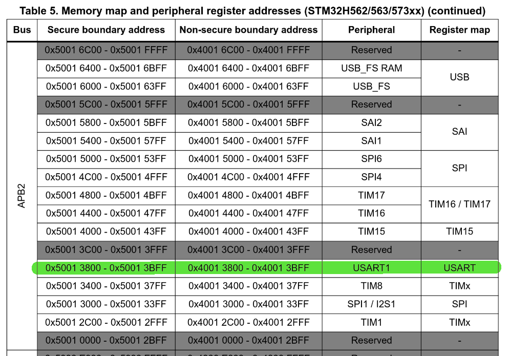
USART1 already tells us then which USART port to look at, but while we’re here, its definition follows the convention of laying out peripheral addresses as a series of pointer casts to structs that divide up the register space as fields, which is worth taking a look at:
//Drivers/CMSIS/Device/ST/STM32H5xx/Include/stm32h573xx.h
#define USART1                         USART1_NS
...

#define USART1_NS              ((USART_TypeDef *) USART1_BASE_NS)
...

/**
  * @brief Universal Synchronous Asynchronous Receiver Transmitter
  */
typedef struct
{
  __IO uint32_t CR1;         /*!< USART Control register 1,                 Address offset: 0x00  */
  __IO uint32_t CR2;         /*!< USART Control register 2,                 Address offset: 0x04  */
  __IO uint32_t CR3;         /*!< USART Control register 3,                 Address offset: 0x08  */
  __IO uint32_t BRR;         /*!< USART Baud rate register,                 Address offset: 0x0C  */
  __IO uint32_t GTPR;        /*!< USART Guard time and prescaler register,  Address offset: 0x10  */
  __IO uint32_t RTOR;        /*!< USART Receiver Time Out register,         Address offset: 0x14  */
  __IO uint32_t RQR;         /*!< USART Request register,                   Address offset: 0x18  */
  __IO uint32_t ISR;         /*!< USART Interrupt and status register,      Address offset: 0x1C  */
  __IO uint32_t ICR;         /*!< USART Interrupt flag Clear register,      Address offset: 0x20  */
  __IO uint32_t RDR;         /*!< USART Receive Data register,              Address offset: 0x24  */
  __IO uint32_t TDR;         /*!< USART Transmit Data register,             Address offset: 0x28  */
  __IO uint32_t PRESC;       /*!< USART Prescaler register,                 Address offset: 0x2C  */
} USART_TypeDef;
...
#define USART1_BASE_NS           (APB2PERIPH_BASE_NS + 0x3800UL)
...
#define APB2PERIPH_BASE_NS       (PERIPH_BASE_NS + 0x00010000UL)
...
#define PERIPH_BASE_NS           (0x40000000UL)
(Note the order of the definitions has not been maintained in the last snippet)
This already tells us a lot about how USART works: by showing us which registers we can play with; that UART1 is on the APB2 peripheral bus, and (with a bit of arithmetic) that it’s register space starts from 0x40013800 (this will come in handy later). A quick glance at RM0481 confirms this:
Now, where does USART1 go? To understand more about this, we’ll turn to the discovery kit’s user manual, UM3143, and see the first mention of USART1 is in the hardware block diagram:
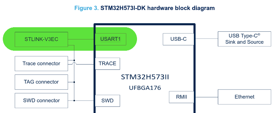
Virtual COM port
So we see that USART1 is connected to STLINK-V3EC. Chapter 8 of UM3143 gives some information about what the STLINK-V3EC is and a link to TN1235, a technical note regarding STLINK debugging devices. STLINK-V3EC is a special debugging device built into the devkit (and itself powered by an STM32Fxx chip!) that provides, among other things, a “virtual COM port”, or VCP for short.
According to wikipedia:
A virtual serial port is a software representation of a serial port that either does not connect to a real serial port, or adds functionality to a real serial port through software extension.
The debugger, which itself is wired up to one of the USB-C connectors on our board, presents itself as a USB CDC-ACM device to the host’s operating system (in my case, Linux). Being a part of the USB specification, there is nothing special that has to be installed on the OS (at least for Linux and MacOS, according to TN1235c, Windows is a different story). Once connected, a device will then appear in the device directory under /dev/ttyACMx, (in my case, I’m seeing /dev/ttyACM0) corresponding to the USB CDC-ACM device class. The software provided by the OS that can interpret the serial USB CDC-ACM interface is, as far as I understand, the virtual COM port!
So now we’ve made it to our host machine, the last thing we have to do is read the device somehow! For this we’ll need a serial console (I chose to use picocom, although any will do), and then we need to configure the connection in our console to match that of the STLINK-V3EC, which we find in UM3143, section 14.7:
The VCP configuration is the following:
- 115200 b/s
- 8-bit data
- No parity
- 1 stop bit
- No flow control
Using picocom, I set up an alias like so:
alias stm32_log='picocom -f n -y n -b 115200 -d 8 -p 1 --imap lfcrlf /dev/ttyACM0'
And now compiling and flashing our project, we finally see our print statements!
cmake --build --preset Debug
STM32_Programmer_CLI -c port=SWD -w build/Debug/poor-mans-printf.elf -v -rst
stm32log
...
Terminal ready
Welcome to STM32 world!
Welcome to STM32 world!
Welcome to STM32 world!
What’s even cooler is that we can even send data back to the MCU from our serial console using scanf!
The extra mile
Of course, for such a simple operation, we’re using an awful lot of code and build logic:
cmake --build --preset Debug
Memory region         Used Size  Region Size  %age Used
             RAM:        2184 B       640 KB      0.33%
           FLASH:       29420 B         2 MB      1.40%
Can we do better? How hard could it be to send characters ourselves over UART?
From this point on, I’m going to assume a basic understanding of UART, as there are plenty of good resources elsewhere describing how it works. Ben Eater’s YouTube video on the RS232 protocol is a great place to start. For our purposes, it should suffice to understand what the TX and RX lines are for.
Looking at the RM0481 section on U(S)ART, we’re a nice block diagram of the UART peripheral architecture:
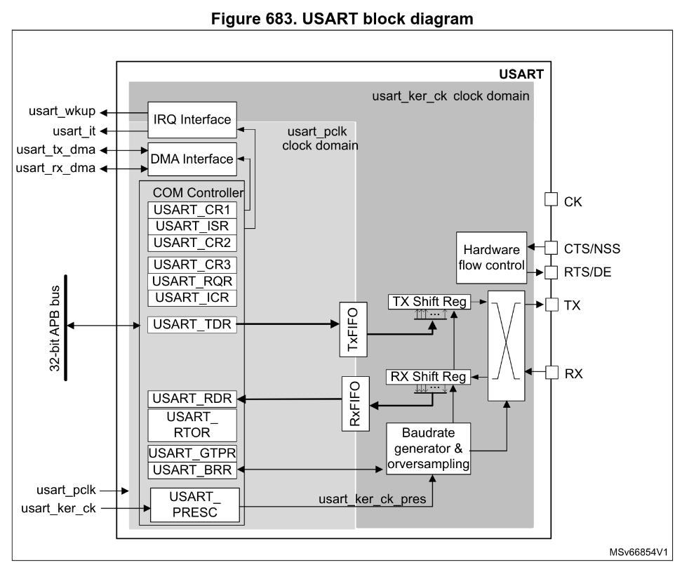
Which shows where the control registers are located, the two different clock domains and how a signal makes its way to the RX and TX lines.
So how do we program it? Looking a bit further down in section 50.5.6, we’re given a list of steps for carrying out single-character transmission:
- Program M bits in
USART_CR1to define the word length,- Select desired baud rate using
USART_BRR,- Program the number of stop bits in
USART_CR2,- Enable UART by writing the
UEbit inUSART_CR1,- Select DMA enable (DMAT) in
USART_CR3,- Set the
TEbit inUSART_CR1to send an idle frame as the first transmission,- Write the data to send in the
USART_TDR, repeat for each word to be transmitted,- When the last data is written, wait until
TCis equal to 1
This seems like a fair bit to do, but fortunately for us, the default values after reset for many of the parameters we need to set to match our Virtual COM port settings are exactly what we need.
For example, we see in 50.8 in the UART register map, that USART_CR1 and USART_CR2 have a reset values of 0x00000000. Looking at the M bits (bits 28 and 12), when both have a value of 0, we’re left with each word containing 1 start bit, 8 data bits and n stop bits. Similarly, when the stop bits (bits 13:12 of USART_CR2) have a value of 0, we’re left with a single stop bit per word. Exactly what we need, so we can leave out steps 1 and 3 altogether!
We also don’t need DMA for this example, se we can skip step 5, and we won’t bother with doing any cleanup here, so we can skip step 8 too. That leaves us with steps 2, 4, 6 and 7, all of which are just setting register values, while step 7 needs to also check a register value.
There is, however, some initialization that we need to do which is unfortunately not documented anywhere in the USART section and requires a bit more background knowledge.
I/O alternate functions
If we recall from our first article in the bare-bones blinker series, we showed the diagram from the datasheet detailing all of the pinouts (ball connections) from the SoC package:
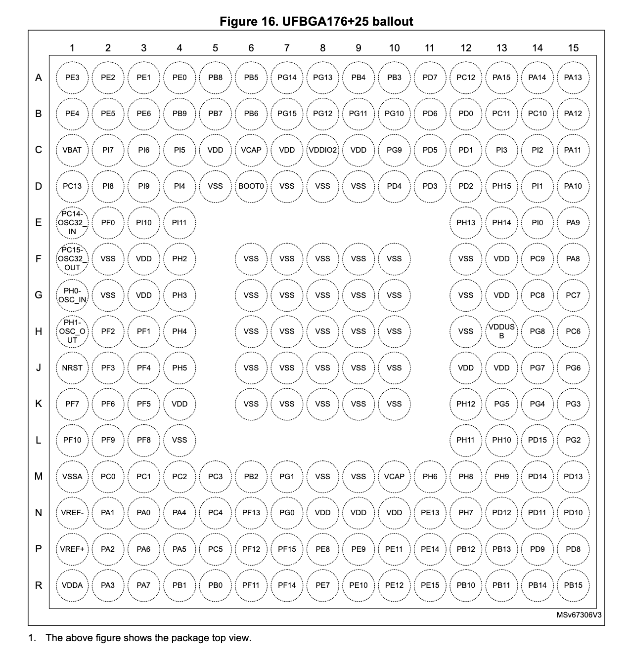
All of the pins starting with P correspond to a GPIO port. Then there pins for a few special signals and power supply (e.g. all the VSS pins, NRST etc.). But notice there are no UART1 pins. Or pins for any other I/O for that matter. This is because the pins are actually shared between the GPIO ports and the on-chip peripherals!
From section 13.3.2 in RM0481:
The device I/O pins are connected to on-board peripherals/modules through a multiplexer that allows only one peripheral alternate function (AF) connected to an I/O pin at a time. In this way, there is no conflict between peripherals available on the same I/O pin
This multiplexer is actually visible in the GPIO circuit diagram in section 13.1:
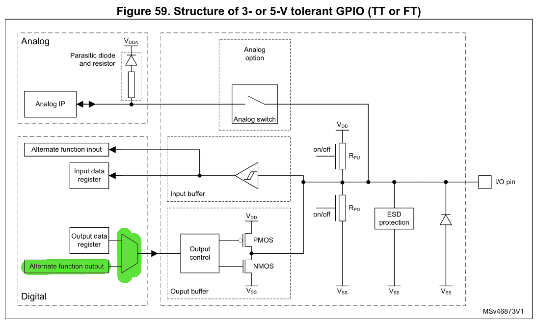
So essentially, the physical pins themselves are controlled by the GPIO control logic, but they can be set to AF mode to allow other peripherals access to the outside world. Unfortunately for us the default mode for GPIO pins is analog mode, not AF mode. So we have some configuration to do!
To find out which GPIO pin we need to configure, we need to turn to the datasheet (RM0481 is agnostic to the package and thus pin layout!). There, we find in section 4.3 the table specifying the alternate functions and the GPIO pins that correspond to them. On the very first page, we see USART1_TX that corresponds to AF7 on port PA9. (We’ll ignore USART1_RX for now, as we only need to send characters).
There is another port, PB14, that can also be configured with AF4 to allow USART1_TX, however, according to the dev kit’s user manual, the STLINK-V3EC is connected to USART1 via PA9/10, so we’ll stick with that one.
Okay, looking at section 13.3.2 of our trusty RM0481, in order to configure AF mode for a GPIO pin, we need to set the GPIOx_MODER register to AF mode, and then set either GPIOx_AFRL|H to configure exactly which of the AFs should be enabled on a given pin. This part is a little confusing due to the way things are numbered but we pick the AFRL|H register based on the index of the pin we’re targeting. Since our target pin is PA9, and 9 falls in the upper half of 0-15, we need to set AFRH.
Each pin in the AFRH is assigned 4 bits, which in turn combine to give one of 16 AFs (0b0000-0b1111). We saw already in the table in the datasheet that we need AF7, so we we’ll set the value 0b0111 when we’re ready.
Before we can do any of this though, we also need to set the GPIOA clock gate to on in the RCC_AHB2ENR (GPIO is located on the AHB2 bus), and similarly, before we can start sending our bytes, we’ll need to enable the clock for UART1, which is located on the APB2 bus, as we saw above.
Calculating USART_BRR
Moving on to our actual UART transmission, step 2 requires that we set the desired baud rate in USART_BRR. Section 50.5.8 describes how we do this. More accurately put, we actually want to calculate the value USARTDIV, which is the ratio of the USART kernel clock speed to the desired baudrate:
For our purposes, we won’t bother with OVER8 sampling, and since we haven’t changed any clock speeds on the board, our value for usart_ker_ck_pres is the same as the default clock speed of 32MHz.
For our desired baudrate of 115200b/s, we then get a value of 32000000 / 115200 = 278, or 0x116.
Waiting on the TXE flag
The last piece of the puzzle appears in step 7, as we have to wait for the UART to be ready before we can transmit anything. This process is described very well in 50.5.6 with the help of this diagram:
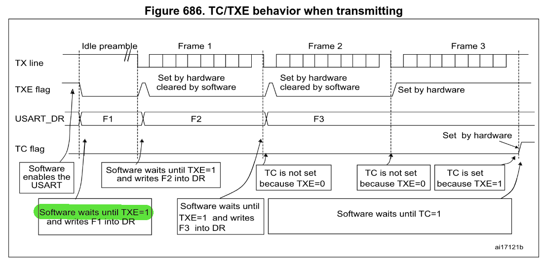
We see here that every time something is transmitted over TX, once the hardware is finished, it sets the TXE flag to 1 to indicate that it’s safe to load the next character into data register. So that’s what we’ll have to do. The TXE flag is located in the USART_ISR register.
Codez
So, so so… with all that in place, let’s put together our little assembly program:
@; uart.s
.syntax unified
	.cpu cortex-m33
	.thumb

.section	.isr_vector,"a",%progbits
	.word	0x0
	.word	main

.data
hello: .ascii "Hello, World!\n"

@; RCC base addr => 0x44020C00
@; GPIOA base address => 0x42020000
@; USART1 base addr => 0x40013800
.text
main:
	@; Step 0: Enable USART I/O pins and clock
	@; Enable GPIOA clock to configure PA9
	ldr r0, =0x44020C8C	@; RCC_AHB2ENR address
	mov r1, #(1 << 0)		@; GPIOA gate at bit 0
	str r1, [r0]

	@; Set PA9 to alternate function mode (MODER[19:18] = 0b10)
	@; Here, we need to keep in mind that by default,
	@; GPIO pins are in analog mode, which is 0b11, not 0b00.
	@; The debug SW debug pins (A13|14|15) are
	@; also set to AF mode, so we also need to be careful
	@; not to inadvertantly overwrite them,
	@; or else we lose our connection to the debugger!
	ldr r0, =0x42020000		@; GPIOA_MODER address
	ldr r1, [r0]
	bic r1, r1, #(0b11 << 18)	@; Clear bits 19:18
	orr r1, r1, #(0b10 << 18)	@; Set to alternate function (0b10)
	str r1, [r0]

	@; Set PA9 alternate function to AF7 (USART1)
	@; Again, being careful not to mess up the SW debug pins.
	ldr r0, =0x42020024		@; GPIOA_AFRH address (AFR[1])
	ldr r1, [r0]
	bic r1, r1, #(0xF << 4)		@; Clear AFR9 bits [7:4]
	orr r1, r1, #(7 << 4)		@; Set AF7 for USART1
	str r1, [r0]

	@; Enable the USART1 clock
	ldr r0, =0x44020CA4		@; RCC_APB2ENR address
	mov r1, #(1 << 14)		@; USART1 gate
	str r1, [r0]

	@; Step 2: Set the baud rate to 115200
	ldr r0, =0x4001380C		@; USART1_BRR address
	mov r1, #0x116			@; 32Mhz / 115200 = 0d278
	str r1, [r0]

	@; Step 4,6: Enable the UE and TE bits
	ldr r0, =0x40013800		@; USART1_CR1 address
	ldr r1, [r0]
	orr r1, r1, #(1 << 0)		@; Enable the UE bit (bit 0)
	str r1, [r0]
	orr r1, r1, #(1 << 3)		@; Enable the TE bit (bit 3)
	str r1, [r0]

	@; Step 7: Write the data to TDR when TXE is ready (=1)
print:
	ldr r0, =14				@; The length of our string
	mov r1, r0				@; r1 will be our counter

next_char:
check_txe:
	ldr r2, =0x4001381C		@; USART1_ISR address
	ldr r3, [r2]
	and r3, r3, #(1 << 7)		@; TXE flag is bit 7 (when FIFO is disabled)
	cmp r3, #(1 << 7)
	bne check_txe

	ldr r2, =0x40013828		@; USART1_TDR address
	ldr r3, =hello

	sub r4, r0, r1
	ldr r5, [r3, r4]
	str r5, [r2]

	subs r1, #1
	bne next_char


	ldr r1, =0x7A1200			@; 8Mx2 cycles for half a second @32MHz
delay:
	subs r1, #1
	bne delay

	b print
We’ll put together our linker script:
//linker.ld
MEMORY
{
  FLASH    (rx)    : ORIGIN = 0x8000000,   LENGTH = 2048K
}

SECTIONS
{
  .isr_vector :
  {
    . = ALIGN(4);
    *(.isr_vector)
    . = ALIGN(4);
  } >FLASH

  .text :
  {
    . = ALIGN(4);
    *(.text)
    . = ALIGN(4);
  } >FLASH

  .data :
  {
    . = ALIGN(4);
    *(.data)
    . = ALIGN(4);
  } >FLASH

}
Assemble, flash and watch our serial console:
arm-none-eabi-gcc -mcpu=cortex-m33 -T "linker.ld" -nostdlib -Wl,--print-memory-usage uart.s
STM32_Programmer_CLI -c port=SWD -w a.out v -rst
stm32_log
...
Terminal ready
Hello, World!
Hello, World!
Hello, World!
And there we have it, the simplest possible code we could write to transmit bytes through UART, through the STLINK debugger and into our terminal. And it all came it at 176B flashed to the device, a reduction of 99,4% of the code generated for us! Of course, we can’t do any fancy formatting, or receive characters, but who needs that right now anyway 😉
If you followed along, I hope you learnt a thing or two about how UART works, about how GPIO is the gatekeeper for all other peripherals, and maybe a little more about assembly too. Next time we’ll try to come up with a similarly simple experiment for DMA and see just how much we can get out of UART!
Cheers.